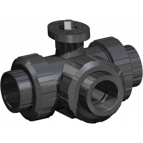
GENERAL FEATURES: • Valve with 3 seats for mixing and diverting processes. It’s possible to select two ways and shut off flow in the third way. • Working temperature: from 0°C to +60°C • Working pressure: see diagram. • Applications: chemicals and all kind of fluids compatible with PVC. • Connections:
Female threaded as per DIN/ISO 228/1;
to be glued as per ISO 727 UNI EN 1452
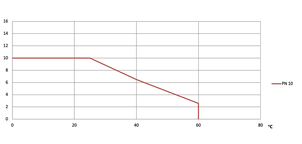
• PN 10 till 25°C if classified chemical resistant with the used fluid
ON REQUEST: • Please contact our sales department.
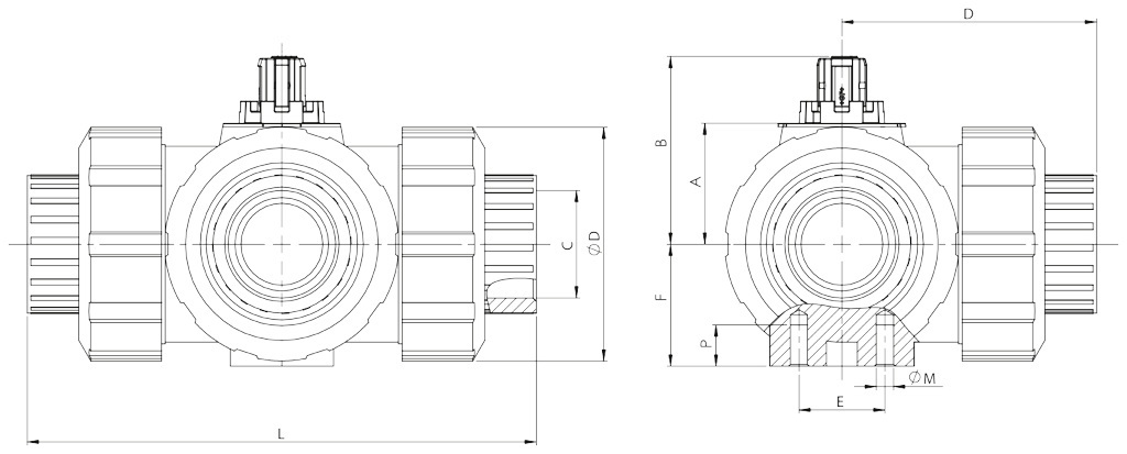
DIMENSIONS
SIZE
A
B
C Threaded
C Glued
D Threaded
D Glued
E
F
L Threaded
L Glued
øM
P
øQ
DN [mm]
[inch]
DN 10
3/8"
26,1
41
3/8"
16
54
52
25
28
113
109
6
8
50
DN 15
1/2"
26,1
41
1/2"
20
56
54
25
28
117
112
6
8
50
DN 20
3/4"
30
48,5
3/4"
25
66
64
25
32
135
131
6
8
58
DN 25
1"
35,2
55
1"
32
74
72
25
36
155
151
6
8
68
DN 32
1" 1/4
44
66,9
1" 1/4
40
89
90
45
45
179
181
8
9
84
DN 40
1" 1/2
50,2
73,1
1" 1/2
50
102,5
105
45
51
201
205
8
9
97
DN 50
2"
62
89,4
2"
63
130,5
133,5
45
65
255
261
8
9
124
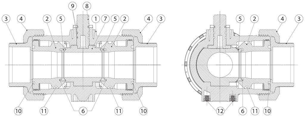
MATERIALS
1
Body
PVC-U
2
Ball sealing support
PVC-U
3
End
PVC-U
4
Nut ring
PVC-U
5
Ball sealing
PTFE
6
Backing seal
EPDM
7
Ball
PVC-U
8
Stem
PVC-U
9
Shaft o-ring
EPDM
10
Valve end seal
EPDM
11
Body seal
EPDM
12
Mounting insert
S.S.
Pressure/temperature diagram
Flow-pressure loss diagram and Kv nominal coefficient
"L" PORT
DN10
DN15
DN20
DN25
DN32
DN40
DN50
Kv100
50
75
150
280
480
620
1230
KV100 liters per minute
KV
3
4,5
9
16,8
28,8
37,2
73,8
KV cubic meters / hour
"T" PORT
DN10
DN15
DN20
DN25
DN32
DN40
DN50
Kv100
140
200
470
793
1290
1910
3100
KV100 liters per minute
KV
8,4
12
28,2
47,2
77,4
114,6
186
KV cubic meters / hour
Kv is the coefficient, expressed in m3/h (with water at 15°C) causing a pressure loss of 1 bar.
BREAKAWAY TORQUES Nm
SIZE
DN 10 3/8"
DN 15 1/2"
DN 20 3/4"
DN 25 1"
DN 32 1"1/4
DN 40 1"1/2
DN 50 2"
PN 10 bar
2
2
3
4
5,5
7,5
10
Torque can vary depending on temperature and type of fluid; a safety factor of 1.4 must be applied. Torque can drop on high frequency of operations. The actuator/valve sizing, indicated on the fol- lowing pages, are based for valves to be used with liquids or gaseous fluids, clean, and for medium temperatures. For further information, or different uses please contact our sales department.
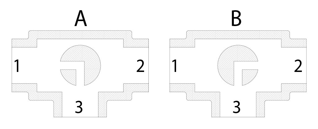
Plan for "L" port
N.B.: “A” must be the rest position of the ball with SR FAIL CLOSE actuator. “B” must be the rest position of the ball with SR FAIL OPEN actuator.
View from above
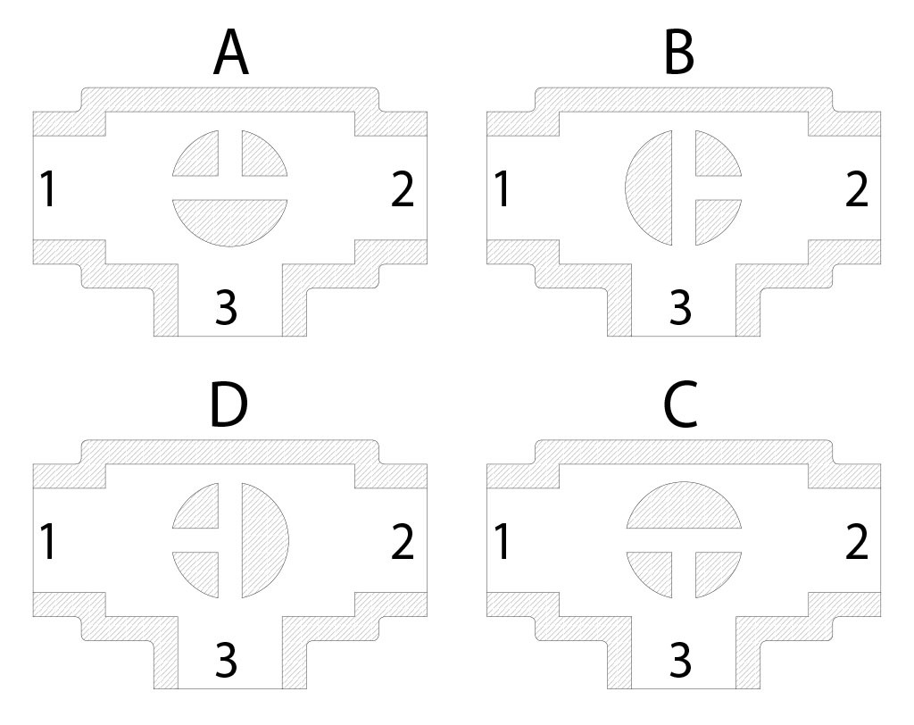
Plan for "T" port
With actuator 2 positions with 90° rotation are possible only: the configuration of the ball must always be communicated at our sales department.
N.B.: Choose the rest position of the ball with SR FAIL CLOSE actuator; whenever supplied with air, actuator turns in an anticlockwise direction. Choose the rest position of the ball with SR FAIL OPEN actuator; whenever supplied with air, actuator turns in a clockwise direction.